This page contains the online version of the manual that comes with the MB8719-2 add-on board
It is illegal in many countries to transmit outside of the normal CB band, this board is to be used for RX only, do not transmit out side of the legal band, you are responsible for the manner in which you use the conversion board.
This board will provide the full coverage that the PLL can produce, without
any gaps.
There are different versions of the MB8719 chassis, there is a single conversion,
dual conversion, AM only and multimode types, they use slightly different
programming on the PLL and a different loop mixer crystal frequency, some
radios use the RCI8719 or MB8734 which are different to the MB8719, pin 10
of these PLL’s is disabled so they have less coverage, this board can
not do the same coverage with them and so is not recommended for the RCI8719
or MB8734 PLL, although it will work with limited results, this board works
on some multimode export types, although it was not designed for them.
I will refer to “single” and “dual” conversion radios
throughout this manual, single conversion is when the radio does not use a
455kHz second I.F. Dual conversion radios have a 455kHz second I.F. stage
and have an alternative loop crystal frequency and binary codes.
If the board is installed in a single conversion radio (such as the President
Washington) you will get the New Zealand band, channels 10 to 40 on low-low,
low, mid (FCC), channels 1 to 3A on high and a 10kHz shift on all bands !
If the board is installed in a dual conversion radio (such as the Cobra 148GTL
or President Grant) you will get channels 26 to 40 on low, mid (FCC), high,
channels 1 to 19 on high-high, the UK band, and a 10kHz shift on all bands
!
You can choose which options you wish to use, it is up to you which functions
you use, I have built as much data into the EPROM as I could fit on it so
that there are lots of options to be used.
This board is not suitable for some radios, please read further in this manual
to see if your radio can use this version of the board, (I can make custom
boards at an additional cost).
A degree of electronic skill is required to install this expansion board, also the radio may need to be tuned or broad banded to allow for the extra frequency coverage that this board will allow.
I have made a quite simple installation look complex, please do not be concerned
about the complexity of this manual, once you know the chassis type used in
your radio you just cross check it against the programming chart I have included.
I have tried to include as much information as possible in this manual to
try and cover all possible requirements and radios, I am sure that there will
be times when some people will need more information or assistance and when
this occurs I can be contacted either through my web site at https://www.radiomods.co.nz/
or by mailing me
This board was designed to convert these radios:
Cobra 140GTL, 142GTL, 148GTL, 2000GTL, Courier Galaxy, Midland 79-900, Pearce
Simpson Super Bengal MkII, President (aka Uniden) Grant (PC409), Grant XL,
Jack, Madison, McKinley, P400, Washington, Realistic (AKA Radio Shack) TRC450,
TRC490, Robyn SB505D, SBE LCBS-8, LCMS-8, Teabury Stalker IX, XV, XX, Tram
D80, D300.
And others as long as the binary codes match and the board physically fits
in the radio, for the board to function correctly the PLL must be using one
of these binary code ranges:
15-59 (CH1-CH40), for single conversion chassis types, using a 11.1125 MHz
crystal.
79-123 (CH1-CH40), for dual conversion chassis types, using a 11.3258 MHz
crystal.
To be technically correct these binary numbers are wrong, although this is
the code input to the PLL pins, pin 10 actually switches between +64 (when
high) and +128 (when low), so the code ranges are actually:
143-187 (CH1-CH40) with pin 10 low
79-123 (CH1-CH40) with pin 10 high
For now you can ignore this detail and think of pin 10 like an inverted +64
bit pin as this is essentially how it functions.
The coverage that should be available after conversion is as follows:
For single conversion radios:
New Zealand CB band, channels 10 to 40 on low-low, low band, mid (FCC) band, channels 1 to 3A on the high band and a +10kHz shift on all bands !
For dual conversion radios:
Channels 26 to 40 on low band, mid (FCC) band, high band, channels 1 to 19 on the high-high band, the UK 27/81 CB band, and a +10kHz shift on all bands !
If you would like different coverage, say you have a single conversion type
with a range of 15-59 and you want the same coverage as the dual conversion
type, change the 11.1125MHz crystal for a 11.3258MHz and invert the input
for the EPROM pin that tells it what type it is used in.
When I installed this board in a Washington (PC385) I got the following coverage:
26.330 - 26.770 NZ “NEW band” With “NZ” band on, clarified
26.175 - 26.505 L-Low “NEW partial band” With “Down 2”
band on
26.515 - 26.955 Low “NEW band” With “Down” band on
26.965 - 27.405 Mid, FCC “C band” Normal band
27.415 - 27.445 High “NEW partial band” With “Up” band
on
For radios in NZ that have been converted with a crystal swap to a 10.900MHz
crystal you can get the same range but the end frequencies will be 0.635MHz
lower, so the “Normal” band will be 26.330-26.770, “Down”
will be 25.880-26.320 etc. you could always get a 11.1125 MHz crystal and
convert it back to standard so that you get the coverage I designed it for.
I originally got my binary code information from the great books written by Lou Franklin (www.cbcintl.com), I recommend you get his books if you want to know more about how these CB’s work.
To work out the binary code just measure the voltage on pins 10 through to
16 of the PLL with the radio on channel 1 mid (FCC) band.
For a code of 15 pins 16, 15, 14 and 13 will be at 8V.
Pins 12, 11 and 10 will be at 0 V, this shows the radio is a single conversion
type.
For a code of 79 pins 16, 15, 14 13 and 10 will be at 8V.
Pins 12 and 11 will be at 0 V, this shows the radio is a dual conversion type.
Some multimode radios use two sets of codes depending on the band, check the
codes again on the other bands, this board was not designed with these radios
in mind, the board may work on other models as long as the binary codes match
those listed. From now on the bands shall be referred to as:
New Zealand - NZ
Down 2 - Low -Low
Down - Low
Mid (FCC) - Normal
Up - High
Up 2 - High - High
UK 27/81 - UK
Please note that I am not able to test this unit in every make and model,
but as long as the binary codes match the ones I listed you will have no problems.
OK, now on to the nuts and bolts (or is the resistors and capacitors ?)....
Be careful when handling the EPROM, it is a static sensitive device and may be damaged if care is not taken to avoid static build up, whenever you pick up or put down the device ALWAYS touch the surface first so that static does not pass through the device, the best thing is to use a antistatic wrist strap at all times.
After doing this you should have the board connected to +12V, earth, 7 outputs from the EPROM to the PLL (D0-D6), 6 inputs from the cut tracks on the channel selector side to the inputs of the EPROM (A0-A5), the conversion type (single or dual) set up on A6, the EPROM control lines connected to your switches:
A7 = DOWN band (or DOWN and UP 2),
A8 = UP band (or UP and DOWN 2),
A9 (+A7/A8) = NZ/UK band,
A10 = +10kHz step.
See the programming chart later in this manual for a completely
comprehensive listing of control functions and binary codes required.
Turn the radio on and test everything thoroughly, all bands, both existing and new, Down band, Up band, NZ/UK and 10K shift on each.
Tune or broad band anything that needs adjusting (see tips later in manual)
If all is OK and you did not make any mistakes, CAREFULLY ! Heat shrink the EPROM board with the tube supplied, do not apply too much heat.
Close up the radio and enjoy your new frequencies !
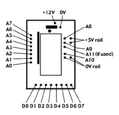
This picture shows the EPROM board wiring diagram with its inputs (A0-A6) its programming / switch inputs (A7-A10, (or All if fitted with a 2732 EPROM) and the 5V, 0V rails), its outputs (D0-D7) and its power supply connections (+12V and 0V).
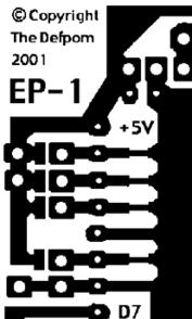
This picture shows the PCB layout, I have used pull down resistors
on the board to simplify the boards installation.
To control one of the programming lines just connect a wire to the required
line, A10 for example, it is the control line for the 10 kHz shift, just pull
it high (5V) and it will activate it.
You must only use the 5V supply that comes from the EPROM board itself for all
programming switches, this is very important as you must not use too high a
voltage otherwise you will damage the EPROM.
The 5V rail is the one going down the left side, the 0V is the one that is horizontal
above D7 and connects to the main earth track, you can also see the pads that
allow the pins to be tied high if needed without having to attach jumper wires
(if a pin needs to be programmed to be high all of the time), you will notice
that for boards using a 2716 EPROM the A11 pin is already pulled high.
The picture below shows the pin-outs of the PLL as viewed from the track-side of the PCB, pin 1 of the PLL is at the top left corner and has a 5V supply going to it.

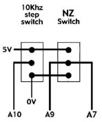
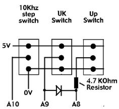
These pictures show various methods of band selection, any one of the switches can be omitted, the NZ/UK switch can be used without an Up / Down band switch, also you can have it set up so that it automatically turns on the Up (for UK) / Down (for NZ) band when you activate it (required for it to work), as longs as diode steering is used to select either the A7 (for NZ) or A8 (for UK) lines when activated.


PLL Pin 10 switching and the EPROM’s A6 input
For proper programming of the EPROM its input A6 must be set to be the same
state as the PLL’s pin 10 was found to be before the modification, so for
a single conversion radio pin 10 is low as standard, because the EPROM board
has pull down resistors across its inputs the A6 input can be left unconnected.
For a dual conversion radio (or radios using the RCI8719 or MB8734) pin 10 is
either pulled high or left disconnected, in this case the EPROM A6 input needs
to be pulled high by using a jumper from the A6 input on the board to the 5V
track on the board.
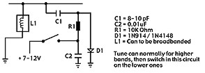
Broad banding
Most radios will not need it to be done, but you may need to, an easy way is
to tune the radio for the upper frequencies (but as low as you can without problems)
and then add the circuit below to the low bands to extend the tuning range of
a problem tuning can.
The clarifier on most of the SSB radios gives about 4kHz of slide, which is
enough for most purposes, but if you want to add a little more then add a 4.7
uH RF coil to the varactor diode, on PC001, PC409 and PC412 it is D35, on the
PC385 it is D37.
The RCI8719 PLL is found in many newer radios, it is pin for pin identicle to
the MB8719 (and MB8734), with the exception of pin 10, on the RCI8719 and MB8734
pin 10 does not function and is pulled high internally, if you intend to install
this board in a radio using them do not connect any wires to pin 10 otherwise
you may damage the PLL, when the board is used with either the RCI8719 or the
MB8734 the EPROM’s A6 input must be pulled high.
Two of the bands covered are only partial bands due to the limitations of the
PLL, this board makes full use of the PLL’s capabilities, one band is used
to access both of the partial bands to simplify the programming and band selection
switches.
For single conversion radios (using the 11.1125MHz crystal) the UP band also
has the DOWN 2 band on it as follows:
Channels 1 through to 3a (channel 3 with the 10kHz shift on) are the UP band.
Channels 10 through to 40 are the DOWN 2 band.
Channels 4 through to 9 will not function as they are out of the PLL range.
For dual conversion radios (using the 11.3258MHz crystal) the DOWN band also
has the UP 2 band on it as follows:
Channels 1 through to 19 are on the UP 2 band.
Channels 26 through to 40 are the DOWN band.
Channels 19a through to 25 will not function as they are out of the PLL range.
This section show you all of the possible programming arrangements with this
EPROM and what input codes allow which outputs from the EPROM board, just look
up the input code range that your radio uses and look at the possible operating
bands and programming information for the board.
For single conversion types A6 needs to be set to 0V (left disconnected)
|
Input code
|
A6
|
A7
|
A8
|
A9
|
A10
|
Output Code
|
Band
|
|
15-59 (single conversion)
|
0
|
0
|
0
|
0
|
0
|
15-59
|
Normal
|
|
0
|
1
|
0
|
0
|
0
|
98-127, 0-14
|
Down
|
|
|
0
|
0
|
1
|
0
|
0
|
60-63, 64-97
|
Up and Down 2
|
|
|
0
|
1
|
0
|
1
|
0
|
79-123
|
New Zealand
|
|
|
0
|
0
|
0
|
0
|
1
|
16-60
|
Normal +10kHz
|
|
|
0
|
1
|
0
|
0
|
1
|
99-127, 0-15
|
Down +10kHz
|
|
|
0
|
0
|
1
|
0
|
1
|
61-63, 65-98
|
Up and Down 2 +10kHz
|
|
|
0
|
1
|
0
|
1
|
1
|
80-124
|
New Zealand +10kHz
|
|
|
79-123 (dual conversion)
|
1
|
0
|
0
|
0
|
0
|
79-123
|
Normal
|
|
1
|
1
|
0
|
0
|
0
|
41+63, 64-78
|
Down and Up 2
|
|
|
1
|
0
|
1
|
0
|
0
|
124-127, 0-40
|
Up
|
|
|
1
|
0
|
1
|
1
|
0
|
15-54
|
UK
|
|
|
1
|
0
|
0
|
0
|
1
|
80-124
|
Normal +10kHz
|
|
|
1
|
1
|
0
|
0
|
1
|
42-63, 65-79
|
Down and Up 2 +10kHz
|
|
|
1
|
0
|
1
|
0
|
1
|
125-127, 1-41
|
Up +10kHz
|
|
|
1
|
0
|
1
|
1
|
1
|
16-55
|
UK +10kHz
|
Please note that some of the code ranges are split into two, this is caused
by two things, the first is the inverted input for pin 10 of the PLL, the second
is when there are some partial bands where the PLL runs out of range, one band
may be used to cover two partial bands, such as “Up” and “Down
2” (for single conversion radios) or “Down” and “Up 2”
(for dual conversion types).
Here are the general functions of the EPROM’s A6, A7, A8, A9 and A10 inputs
(may vary with input code range of radio, see chart for more details):
A6 = Single or dual conversion type selector, low for single, high for dual.
A7 = Down band selector (and Up 2 band for dual conversion radios).
A8 = Up band selector (and Down 2 band for single conversion radios).
A9 = NZ/UK band selector (used in conjunction with A7 (NZ) and
A8 (UK).
A10 = + 10 kHz shift.
A11 = Not used, this pin is used to select the EPROM type that is installed on the board, do not alter the state of this pin otherwise you may damage the EPROM !
If you do not know how to calculate the binary number (also known as ”N”
code) read this.
|
PLL pin number
|
16
|
15
|
14
|
13
|
12
|
11
|
10
|
|
Binary weight
|
1
|
2
|
4
|
8
|
16
|
32
|
64
|
So if pins 13, 14, 15 and 16 where high (at over 5V) and the rest where low (at 0V) you would have a binary code of 15 (1+2+4+8=15), you just ignore the pins that are low.
1. I checked the PLL pins and found that it used the code range
of 15-59 (single conversion type).
2. I decided that I only wanted to have a +10 kHz shift and the
Down band.
3. I checked the programming chart and found that for a code range
of 15-59 the +10kHz step uses A10 and the Down band uses A7.
4. I cut the tracks on the radio PCB for PLL pins 16-10.
5. I made available the switches required for the new functions
and wired them to the EPROM board
6. I connected the EPROM inputs (A0-A6 on the EPROM board) to
the channel selector side of the cut tracks as shown below:
PLL pin number --> 16 15 14 13 12 11 10
Tracks -----> | | | | | | |
Cut in tracks ---> === === === === === === ===
Tracks -----> | | | | | | |
EPROM inputs A0-A5--> A0 A1 A2 A3 A4 A5 A6
Tracks -----> | | | | | | |
Tracks -----> | | | | | |
Connections | | | | | |
to channel selector --> O O O O O O
7. I connected the EPROM outputs (D0-D6) to the PLL pins as follows:
|
PLL pin number
|
16
|
15
|
14
|
13
|
12
|
11
|
10
|
|
EPROM output number
|
D0
|
D1
|
D2
|
D3
|
D4
|
D5
|
D6
|
8. Then I connected the power wires (+12V and 0V) from the board to the radio.
9. I double checked all of my wiring, checked that I had cut the tracks correctly on the EPROM and radio boards and that I had got the input and output connection the correct way around etc.
10. I slipped the EPROM board into its heat shrink tube to protect it.
11. I turned on the radio and checked for both normal operation and the new expanded functions I set up (+10kHz step and the Down band).
12. I checked to make sure that the EPROM board was not receiving a 12V supply after I turned the radio off.
13. All was working correctly so I applied heat to the heat shrink tube to finish the installation.
14. I did not need to broad band the radio, so I have finished the installation.
15. I closed the radio back up.
EPROM is not working at all
Check jumper on pin 21, for a EPROM marked as a 2716 the pin should have a jumper to the +5V rail on the board.
Check that you have not miss-programmed the jumpers or switches, 1 incorrect jumper or selection setting could stop the EPROM recognizing the binary codes.
The radio does not use the correct binary codes required for the EPROM to work in it, see note about binary codes that are supported earlier in this manual.
Only some bands are working
There could be a mistake with the programming switches not giving the EPROM either a 5v or 0V signal, or a jumper has not been cut or added correctly.
You did not notice that the radio uses more than one set of binary codes and you have not set the switches / jumpers for the other codes.
Some channels do not work on a certain band
If there is a large gap of channels missing it may be a short or switch programming problem, some versions will have gaps in the coverage when a band covers a partial band.
Run a knife carefully between the tracks on the EPROM board just incase there is a slight bridge between them, check between the pads where the wires are soldered on.
The EPROM may have been damaged by static electricity during handling or by incorrect wiring.
You may have incorrectly wired either the inputs or the outputs of the EPROM to the radio.
Note: All EPROM’s are checked after programming to ensure that they have accepted the programming information correctly and that the EPROM is not faulty.
E-mail me if you have any questions or concerns about installation.
All boards are installed at your own risk,
(it is not my fault if you make a mistake and damage your equipment).
I build and test these circuits myself before shipping them, so I know that the boards are working correctly when you receive them.
This counter shows the number of hits since the 26th January 2002
Copyright © RadioMods 1997-2024