LC7233 Single-Chip Microcontroller with Built-In LCD Driver and PLL Circuits

Overview
The LC7233 is a single-chip microcontroller for use in electronic tuning applications. It includes on chip both LCD drivers and a PLL circuit that can operate at up to 150 MHz. It features on-chip RAM and ROM, a programmable high-speed divider.

 LCD driver
 6-bits keypad matrix scan output
 Two 4-bits input ports
 Two 4-bits input/output ports
 2-bit open-drain high voltage output
 23 mask-selectable output drivers
 150MHz phase-locked loop
 Programmable high-speed divider
 Program memory (ROM): 4 k words by 16 bits
 Data memory (RAM): 256 4-bit digits
 One 6-bit A/D converter
 Two 8-bit D/A converters (PWM)
 Voltage detection type reset circuit
 PLL: 4.5 to 5.5 V
 CPU: 3.5 to 5.5 V
 RAM: 1.3 to 5.5 V
 64-pin QIP


General programming guidance of LC7233 devices with Seung Yong CPU SYSTEM 501/105.
The processors SYSTEM 501 (105) with label Seung Yong are customized mask-programmed CPU's on base of the LC 7233 CPU from Sanyo.
Those in the following specified possibilities apply only to CPU's with the above Seung Yong designation and not to others! (e.g. also not for the designation SY-002!) Programming are those pin 24, 25, 26 of the CPU.
The indicated bridges must be manufactured from the links indicated in each case to pin 18.
Pin 26 to 18Pin 25 to 18Pin 24 to 18Description
ConnectConnectConnect40 Channels (CEPT) - 26.965MHz to 27.405MHz
OpenOpenOpen80/12 Channels (Germany) - 26.565MHz to 27.405MHz
OpenConnectOpen40 Channels UK - 27.60125MHz to 27.99125MHz
ConnectOpenOpen120 Channels Polish - 26.510MHz to 27.850MHz
ConnectConnectOpen240 Channels Polish - 26.060MHz to 28.750MHz
OpenConnectConnect400 Channels - 25.165MHz to 29.655MHz
ConnectOpenConnect240 Channels - 26.065MHz to 28.755MHz

Consider please:
With 120 to 400 channel programming must be in the device absolutely the CH 9-Taste wired, because this becomes with many channel operation automatically the BAND selection button! With devices with ME key in place of CH 9 the key assignment must be still umgeloetet or converted according to the following list. (devices starting from summer/autumn 1996 have in addition according to characterized solder joints on the inside the front plate circuit board, so that the change without removing the front screen is possible). Otherwise the ME key must be separated two-pole and be soldered on with thin wires to the PIN's 18 and 5 of the CPU.

Key assignment:
AM/FM: Pin 18 to 3SCAN: Pin 21 to 3Hi/Lo: Pin 21 to 4DW: Pin 22 to 5
CH9: Pin 18 to 5CH19: Pin 18 to 6UP: Pin 20 to 5DOWN: Pin 20 to 6
ME: Pin 17 to 4LOCK: Pin 18 to 4Light: Pin 22 to 4

General programming guidance of LC7233 devices with Maycom CPU SYSTEM AH27
The processors SYSTEM AH27 with label Maycom are customized mask-programmed CPU's on base of the LC 7233 CPU from Sanyo.
Those in the following specified possibilities apply only to CPU's with the above Maycom designation and not to others!

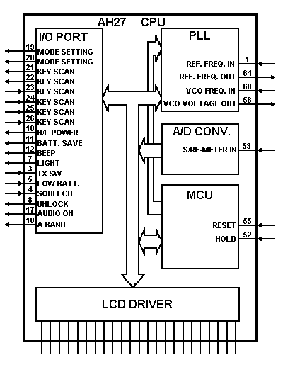
AH27 Block Diagram


This counter shows the number of hits since the 29th January 2000


Go Back To The Components Page

Go Back To The Main Home Page


Copyright © The Defpom 1997-2008

https://www.radiomods.co.nz/