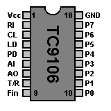
TC9106 Aand TC9119 PLL Frequency Synthesizer

Overview
This 27 MHz band, PLL frequency synthesizer LSI chip is designed specifically for CB transceivers.
The integrated circuit`s incorporates PLL circuitry and a controller for CB applications on a single CMOS chip.
This PLL-circuit use a 8 bit ROM programmable divide-by-N counter. The ROM-table is programmed from factory to 40 channels.
| Pin | Name | Description |
|---|
| 1 | Vcc | Positive Supply Voltage |
| 2 | RI | Referency Oscillator Input |
| 3 | CL | |
| 4 | LD | Loop Detect - Unlocked=LOW Locked=HIGH |
| 5 | PD | Phase Detector Output |
| 6 | AI | Amp. Input |
| 7 | AO | Amp. Output |
| 8 | T/R | Transmit=HIGH Receive=LOW |
| 9 | F in | VCO Frequency Input |
| 10 | P0 | Programmable input 0 |
| 11 | P1 | Programmable input 1 |
| 12 | P2 | Programmable input 2 |
| 13 | P3 | Programmable input 3 |
| 14 | P4 | Programmable input 4 |
| 15 | P5 | Programmable input 5 |
| 16 | P6 | Programmable input 6 |
| 17 | P7 | Programmable input 7 |
| 18 | GND | Ground |
Programming Chart for TC9106
| Channel | RX
Divided by | TX
Divided by |
|---|
| 1 | 3254 | 3345 |
| 2 | 3256 | 3347 |
| .. | .... | .... |
| 22 | 3306 | 3397 |
| .. | .... | .... |
| 40 | 3342 | 3433 |
NOTES:
1. 91-count upshift on TX provides 455kHz offset for receiver IF mixing.
2. Reference and Programmable Dividers use 5kHz steps.
Example of VCO Determination, Channel 1:
3254 x 5kHz = 16.270MHz (RX-Mode)
3345 x 5kHz = 16.725MHz (TX-Mode)
Programming Chart for TC9119
| Channel | RX
Divided by | TX
Divided by |
|---|
| 1 | 3381 | 3472 |
| 2 | 3383 | 3474 |
| .. | .... | .... |
| 40 | 3459 | 3550 |
NOTES:
1. Identical operation principal to TC9106. Only difference is the N-Codes themselves.
2. reference and Programmable Dividers use 5kHz step.
3. 91-count upshift on TX provides 455kHz offset for receiver IF Mixing.
This counter shows the number of hits since the
29th January 2000

Go Back To The Components Page
Go Back To The Main Home
Page
Copyright © The Defpom 1997-2008
https://www.radiomods.co.nz/

