Modifications for the Kenwood TR-2200
Service notes on TR-2200A
Author: Trio-Kenwood Communication, inc.
Service bulletin no. 22 (31-10-1977)
TRANSMITTER
-
No TX RF output: Bad 2SC1169 Q9 on X56-1210-11.
-
No TX: Shield plate touching to circuit board under Q8 driver 2SC741.
-
No TX: Open D2 MI301 on X5501130-01.
-
No TX: Repair broken RCT line from crystal deck to TX oscillator.
-
No TX: Bad Q13 2SA562Y. No T13 voltage on TX X56-1210-00.
-
No modulation: Bad D4 1s1658 on X56-1210-11.
-
No TX: Capacitor C21 lead touching to ground at Q4 on X56-1210-11.
-
No TX: No collector voltage to Q7 Q8. Bad Q15 2SC735 Hi/Low control
for Q14 on X56-1210-11.
-
TX distortion: Check D3 Zener 9 volt supply regulator for TX low
level stages on X56-1210-11.
GENERAL Note On TR-2200A
-
Battery plate overheats: If the red and yellow leads of the external
DC cord are connected together, the battery plate will overheat.
RECEIVER
-
Receive Sensitivity poor: Bad 10.245 MHz xtal on X55-1130-11.
-
Receive Sensitivity poor: Bad MI301 D4 on X56-1080-00.
-
Receive Sensitivity poor: Bad Q1 3SK41L on X55-1130-11.
-
Bo battery operation: Miscontact of internal switch in power jack.
-
No C9 B+ to receiver: Bad Q12 2SC496 on X56-1210-11.
-
Batteries will not charge: Check for a shorted battery plate.
-
Low Rx sensitivity: Bad D3 1S2588.
-
No squelch: Check Q15 2SC458 on X55-1130-11.
-
Poor squelch when cold: Replace D14-16 1N60.
-
No audio: Bad qudio IC NPC575 Q16 on X56-1210-11.
Adapting the TR-2200A antenna to early Trio and Drake Portables.
Author: Trio-Kenwood Communication, inc.
Service bulletin no. 11 (13-1-1977)
We have had several inquiries about adapting the TR-2200A whip antenna to the Drake TR-22C and Trio TR-2200. We now have a kit of parts to do this. Following is a copy of the instruction sheet supplyed with each kit.
TR-2200 Antenna Kit Instructions
| No. | Part Name | Part Number | Qty |
|---|
| 1 | Whip Antenna | T90-0082-05 | 1 |
| 2 | Antenna Connector | J32-0230-04 | 1 |
| 3 | Washer | N19-0282-04 | 2 |
| 4 | Insulating Ring | N19-0283-04 | 2 |
| 5 | Antenna Lug | E23-0097-04 | 1 |
| 6 | Nut | N14-0116-04 | 1 |
| 7 | Pipe | F29-0018-14 | 1 |
| 8 | Ground Lug | E23-0015-04 | 3 |
| 9 | Screw | 3x6 mm | 1 |
| 10 | Cable with Lapacitor | æ | 1 |
- Remove original antenna.
- Enlarge antenna hole to 9.5 mm.
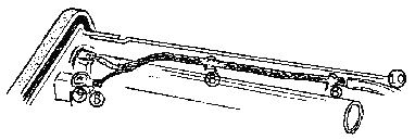
- Install parts 1 thru 8 as shown in the exploded view below.

- Remove coaxial cable that runs from the original whip antenna th the SO-239.
- Connect original coaial cable from terminals ANT and E to the external antenna connector (SO-239). (This cable originally went from terminals ANT and E to the whip antenna.)
- Locate the 2 "L" brackets mounting the TX unit to the side and install 2 ground luge between the bracket and the side out the unit.
- Install the coaxial cable so that the end with the capacitor is aat the SO-239.
- Solder the free end of the capacitor to the center pin of the SO-239 and solder the coax braid to the ground terminal.
- Mount the last ground lug with 3x6 mm screw at the hole next to the whip antenna.
- Solder the braid of the supplied coax to the ground lug instalkled in Step 9 and the center conductor of the coax to the antenna lug 2.
- Carefully solder the coax braid to the 2 lugs installed in Step 6. (See diagram below.)

Go Back To The Kenwood Mods Page
Go Back To The Main Modifications Page
Go Back To The CB / HAM Radio Main Page
Go Back To The Main Home Page
Copyright © The Defpom 1997-2008
https://www.radiomods.co.nz/


