.64 Homebrewed Antenna
-
- Frequent Keyer
- Posts: 69
- Joined: Friday 8th Apr 2011, 1:45
- First Name: Charles
- Location: NW Arkansas
- Contact:
.64 Homebrewed Antenna
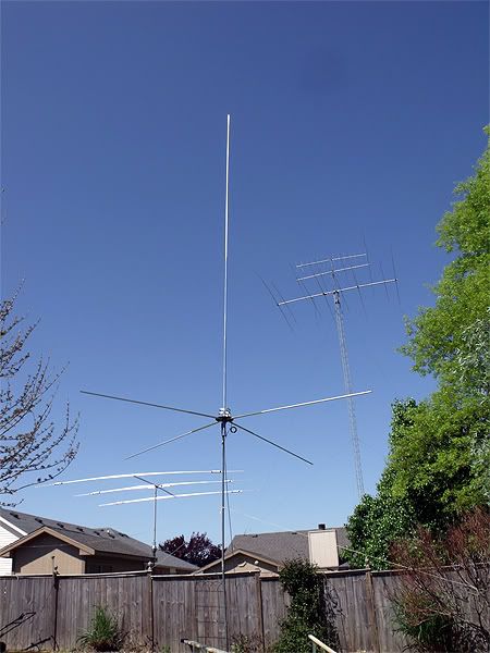
I decided I wanted to put another 5/8λ Omni in the air before I moved on to other antennas, but decided why not go .64 first and see if I like it. To me it looks really short after working with Sigma IV/Vector 4k antennas.
I have to get my photos ready, and post some current results so far with the MFJ-259b. Some of the numbers look good.
Curiously, I am finding that unlike the complaints of the SWR shifting with power applied to the system, there is no such thing going on so far on this antenna. It is holding the 1.1:1 SWR with the meter in either case.
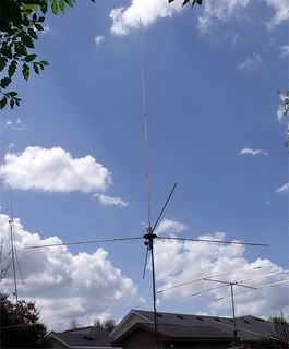
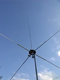
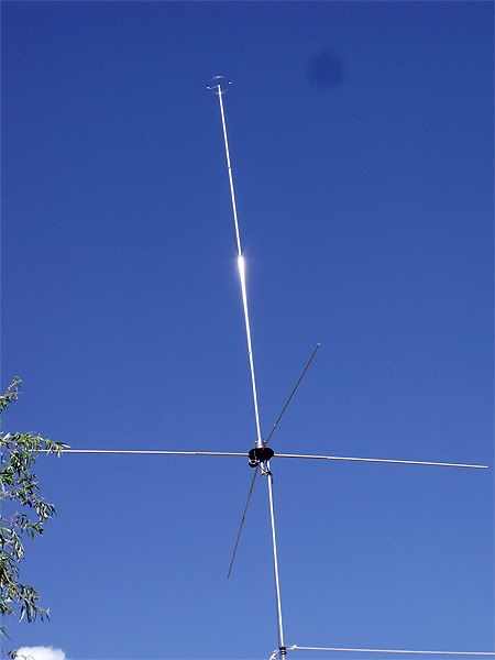
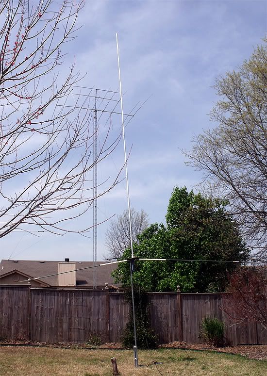
I am working on it at only 8' above ground so things could go South raising it up. We'll see. It's nothing special, 4 radials and a vertical radiator.
I have discarded the idea of using a Gamma on it, and may revisit the dimensions for the Maco style loop. Right now, the only thing working well is a tapped coil.
So far:
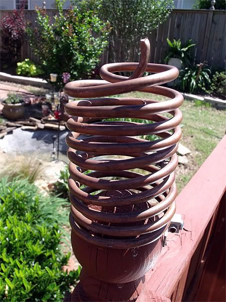
Initially, I'd used this coil which was half the spring from a Dachshund wiener dog letter holder.
Dimensions - 3" x 1.25" x 9 wraps
2.0:1 SWR limits using a small coil:
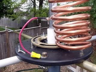
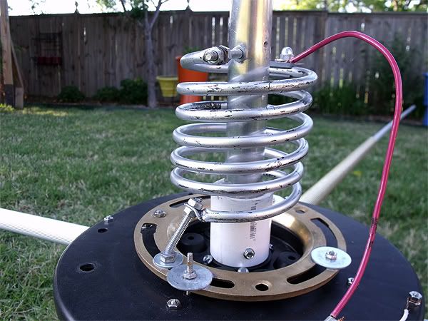
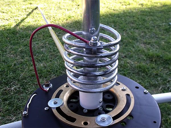
The current Matching System is a large coil:
Dimensions - 6" x 3.25" x 6 wraps.
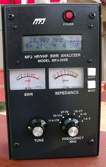
For those interested in the 2.0:1 SWR bandwidth using the large coil.
This coil was first manufactured for use on one of my mobile antennas. It was brake line coiled up for use on the antenna.
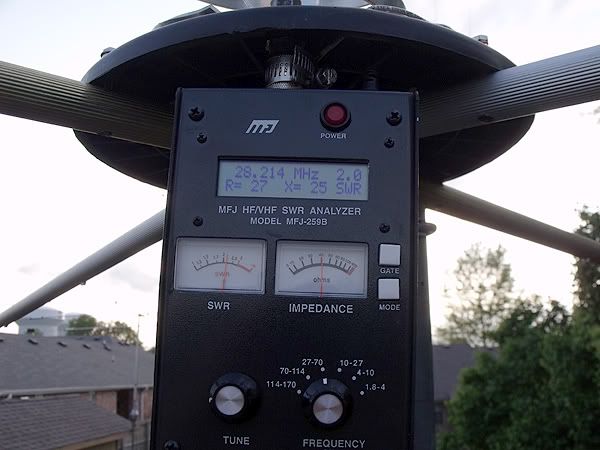
As can be seen on the analyzer, the bandwidth improved with the use of the larger coil.
I have to get my photos ready, and post some current results so far with the MFJ-259b. Some of the numbers look good.
Curiously, I am finding that unlike the complaints of the SWR shifting with power applied to the system, there is no such thing going on so far on this antenna. It is holding the 1.1:1 SWR with the meter in either case.
I am working on it at only 8' above ground so things could go South raising it up. We'll see. It's nothing special, 4 radials and a vertical radiator.
I have discarded the idea of using a Gamma on it, and may revisit the dimensions for the Maco style loop. Right now, the only thing working well is a tapped coil.
So far:
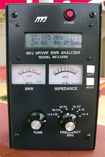
Initially, I'd used this coil which was half the spring from a Dachshund wiener dog letter holder.
Dimensions - 3" x 1.25" x 9 wraps
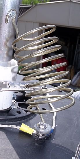
2.0:1 SWR limits using a small coil:
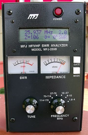
The current Matching System is a large coil:
Dimensions - 6" x 3.25" x 6 wraps.
For those interested in the 2.0:1 SWR bandwidth using the large coil.
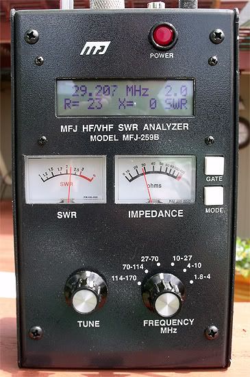
This coil was first manufactured for use on one of my mobile antennas. It was brake line coiled up for use on the antenna.
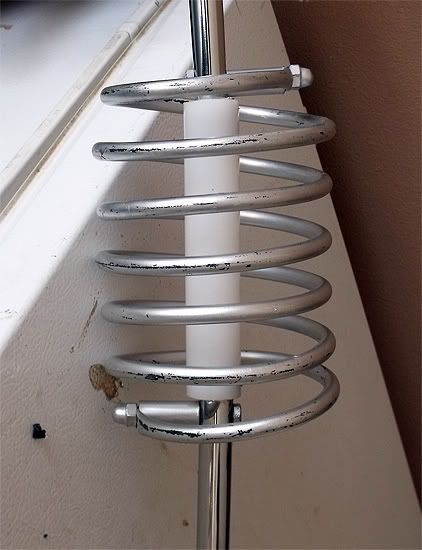
As can be seen on the analyzer, the bandwidth improved with the use of the larger coil.
-
- Frequent Keyer
- Posts: 69
- Joined: Friday 8th Apr 2011, 1:45
- First Name: Charles
- Location: NW Arkansas
- Contact:
Re: .64 Homebrewed Antenna
I raised the antenna up 5' to 13' elevation, and as I had suspected, everything went south. Apparently some ground losses were affecting the match, and the appearance of being good was a result of being too near the earth. So I've been working on improvements in mechanics of the antenna, and it's tune and match.
I have tried for a significant part of the day to get this antenna where it ought to be.
No going there with the current matching system. A .64λ antenna length antenna should by nature be resonant lower than where I operate, so I am not surprised that the only good read from the 259B was on 26.125.
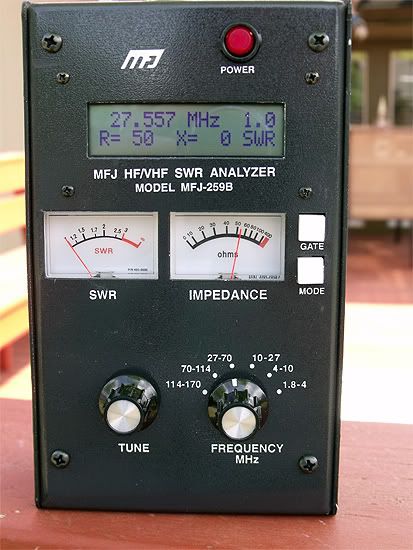
SWR = 1.0
R = 50
X = 0
On 27.400 the best I got today after trying two different coils was with one of smaller coil diameter, and more wraps:
SWR = 1.2
R = 48
x = 8
This was with a vertical length of 22' 10" as opposed to 23'.
Some physical changes were done to improve integrity and appearance of the antenna.
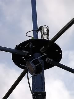
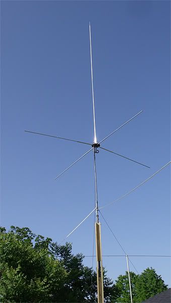
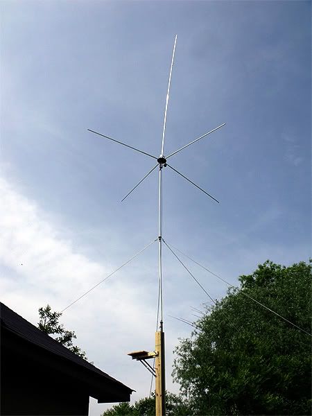
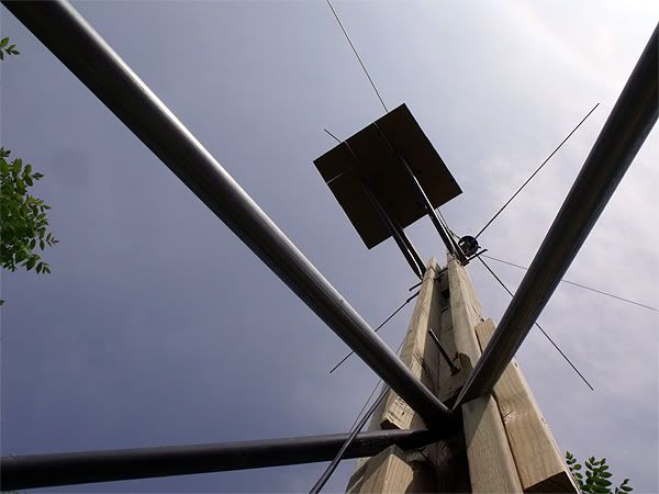
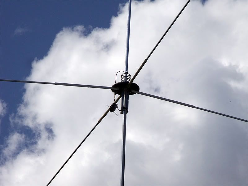
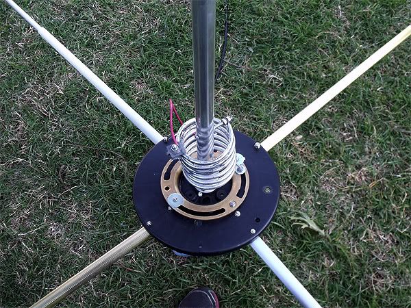
When you look at my photos there is no disputing that this is a homebrew. The brass floor flange is there to add strength to the spool end disc on which the GP radials are mounted, and to serve as the conductor between all the radials.
Re: .64 Homebrewed Antenna
Hi Bro
-
- Frequent Keyer
- Posts: 69
- Joined: Friday 8th Apr 2011, 1:45
- First Name: Charles
- Location: NW Arkansas
- Contact:
Re: .64 Homebrewed Antenna
Hello, Johno. Fancy meeting you here!
I worked on this thing some more today trying to prove to myself it could be done.
Here is what I did and the results.
First using this coil:
2.0 R= 28 X= 21 --------- 28.713
1.5 R= 56 X= 21 --------- 28.108
1.2 R= 61 X= 7 ----------- 27.804 (lowest)
1.2 R= 53 X= 9 ----------- T5
1.2 R= 50 X= 11 ---------- 27.405
1.3 R= 52 X= 14 ---------- 27.185
1.5 R= 61 X= 22 ---------- 26.869
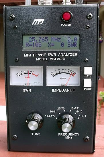
2.0 R= 110 X= 0 ---------- 26.244
Second using this coil:
2.0 R= 28 X= 20 ---------- 28.769
1.5 R= 53 X= 23 ---------- 23.243
1.1 R= 51 X= 5 ---------- 27.706 (lowest)
1.1 R= 52 X= 8 ---------- T5
1.2 R= 49 X= 10 ---------- 27.405
1.3 R= 51 X= 14 ---------- 27.185
1.5 R= 59 X= 22 ---------- 26.884
2.0 R= 110 X= 0 ---------- 26.249
Third using second coil and adding 10" to length to compensate for the portion of the vertical beneath the radials:
2.0 R= 27 X= 19 ---------- 28.814
1.5 R= 51 X= 23 ---------- 28.293
1.1 R= 60 X= 0 ---------- 27.754 (lowest)
1.1 R= 51 X= 6 ---------- T5
1.2 R= 48 X= 9 ---------- 27.405
1.3 R= 50 X= 13 ---------- 27.185
1.5 R= 59 X= 21 ---------- 26.859
2.0 R= 108 X= 0 ---------- 26.225
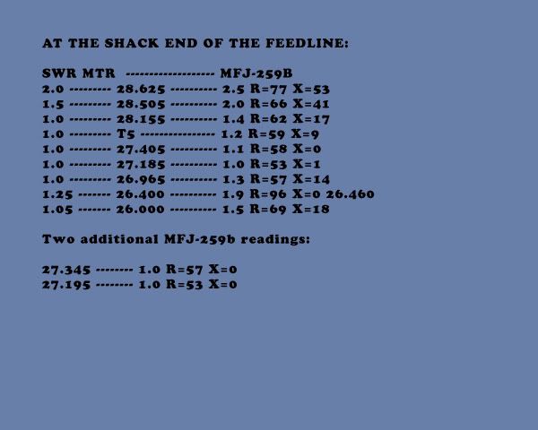
AT THE SHACK END OF THE FEEDLINE:
-
- Frequent Keyer
- Posts: 69
- Joined: Friday 8th Apr 2011, 1:45
- First Name: Charles
- Location: NW Arkansas
- Contact:
Re: .64 Homebrewed Antenna
Taking the readings from within the shack, antenna at 42' height:
28.265 ------------ 2.0 R=61 X=34
27.979 ------------ 1.5 R=49 X=22
27.571 ------------ 1.0 R=45 X=1
27.555 ------------ 1.0 R=46 X=1
27.405 ------------ 1.2 R=49 X=9
27.185 ------------ 1.5 R=55 X=21
26.965 ------------ 1.8 R=74 X=27
26.549 ------------ 2.0 R=108 X=0
It is much narrower banded, and friendly higher up the band.
What the SWR meter in the shack says:
28.485 ------------ 2.0
28.305 ------------ 1.5
27.555 ------------ 1.0
27.405 ------------ 1.0
27.185 ------------ 1.05
26.965 ------------ 1.25
26.800 ------------ 1.45
26.600 ------------ 1.0
Seems the SWR meter has a different point of view on the whole thing.
-
- Frequent Keyer
- Posts: 69
- Joined: Friday 8th Apr 2011, 1:45
- First Name: Charles
- Location: NW Arkansas
- Contact:
Re: .64 Homebrewed Antenna
These readings are on the antenna after I brought it back down to 13' height so I can modify my tip over tower to make it more testing friendly.
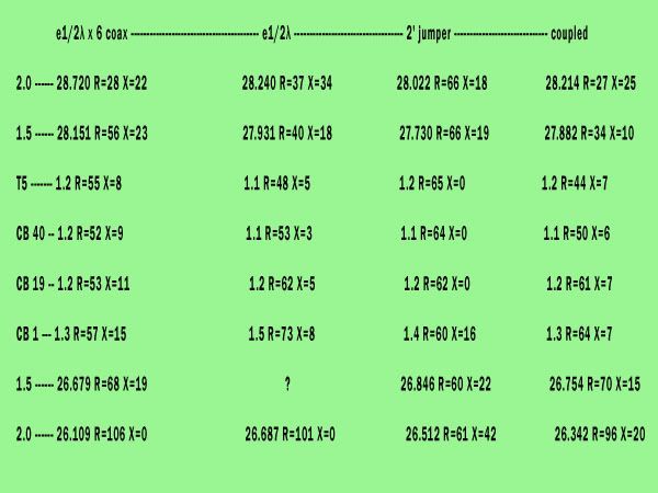
What we have is several readings of the antenna with the latest matching system as previously posted. The readings are 4 different sets consisting of the
MFJ-259B connected to the antenna by e1/2λ x 6 coax, e1/2λ, 2' jumper, and directly mounted to the antenna feed point with a coupler connector.
This time around I found the analyzer behaved as it should directly against the bottom of the radials . . .
Apparently I failed to get a reading at the 1.5 bottom reading in the e1/2λ set,unless it was also 26.965 reading.
-
- Frequent Keyer
- Posts: 69
- Joined: Friday 8th Apr 2011, 1:45
- First Name: Charles
- Location: NW Arkansas
- Contact:
Re: .64 Homebrewed Antenna
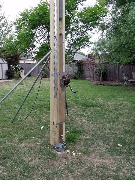
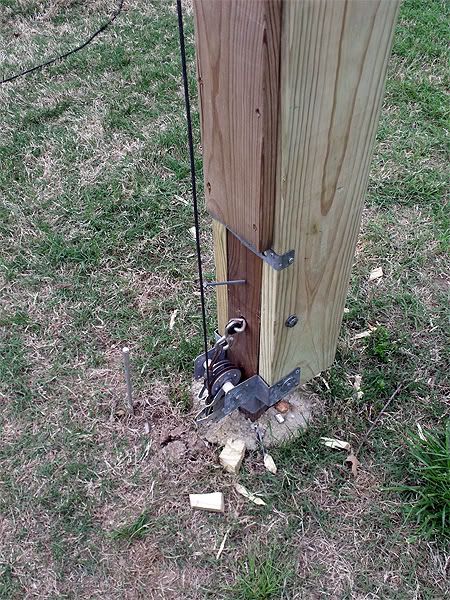
I have made some modifications to the tip over tower that will beef it up.
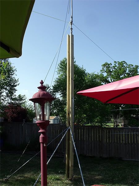
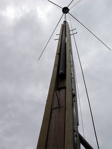
It is now comprised primarily of an ?- beam constructed of treated 2 x 10 x 16' and 2 x 4 marrying them together.
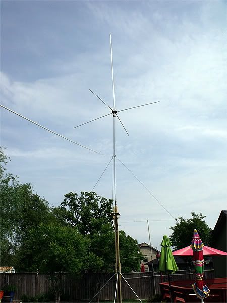
Inside the beam I have mounted my 40' push-up so that the bottom of it is 1' above the break-over point. This allows me to extend the upper 30' of the pole when once I have the mast standing straight up. In the photo there is a 5' additional section of pipe between the top of the PU pole and the antenna which I will be removing in order to kee the antenna within reach when scoped in. i will be adding some ladder spikes in the top of the wooden portion of the mast to stand on so ads to have a better position for extending the PU pole rather than the top of my step ladder.
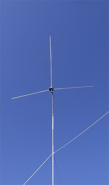
I had to go to work so I didn't get it completed. Soon. BTW, it works quite well so far. In the photo the antenna sits at 23.5'.
-
- Frequent Keyer
- Posts: 69
- Joined: Friday 8th Apr 2011, 1:45
- First Name: Charles
- Location: NW Arkansas
- Contact:
Re: .64 Homebrewed Antenna
I have a little more work to do on the tower to get it where I want it to be.
One more innovation will be an 18" x 30" platform near the top of the wooden section that I can raise when I want to stand up there and work with the antennas, and will fold downward against the side of the tower when not in use. But so far I am adding a few more photos of the tower, and a link to a video of me lowering and raising it.
Almost ready to get back to work on the antenna.
Go to - http://youtu.be/aTuYgahj2ek - or - http://cacirilo.multiply.com/video/item ... Over01.wmv
-
- Frequent Keyer
- Posts: 69
- Joined: Friday 8th Apr 2011, 1:45
- First Name: Charles
- Location: NW Arkansas
- Contact:
Re: .64 Homebrewed Antenna
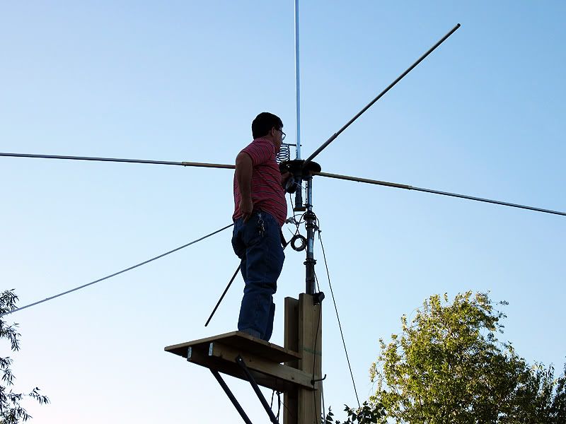
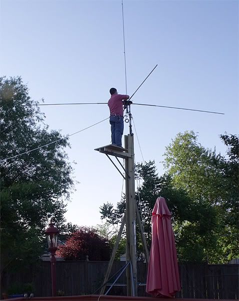
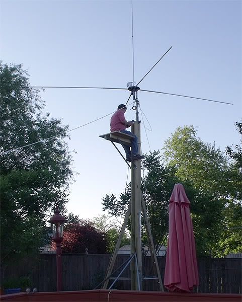
I have added the platform to work from to the top of the wooden section.
As with all things I do, there is a little at each stage that tells me I have a little more to do.
I am going to add some more guys, especially at the top of the wood section, if I'm going to send any time on that platform.
I have been on it already, but want the added assurance that it remains rock steady when I am up there.
-
- Frequent Keyer
- Posts: 69
- Joined: Friday 8th Apr 2011, 1:45
- First Name: Charles
- Location: NW Arkansas
- Contact:
Re: .64 Homebrewed Antenna
Up on the platform working on the antenna again.
-
- Frequent Keyer
- Posts: 69
- Joined: Friday 8th Apr 2011, 1:45
- First Name: Charles
- Location: NW Arkansas
- Contact:
Re: .64 Homebrewed Antenna
Worked on the antenna some more, and not so sure I've noted any improvements from the analyzer standpoint.
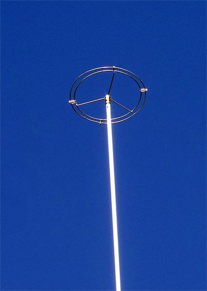
I put on a cap hat just to see if it made any measurable difference. It has an overall diameter of 14".
I had to work at an acceptable shortening length for the antenna vertical, and ended up a mere 10" shorter than previous to installing the thing.
I also went back to a smaller nearly square coil modeled from the Shockwave antenna coil - 4.5" tall x 4" OD x 6 exact wraps. This is around the vertical rather than off to the side as I usually do. It may get changed . . .
I sat on the platform with the antenna at 18.5' and attempted to tune it with the single 1/2λ coax until I felt I was too tired to continue and said good enough for now. 27.400 was a 1.2 SWR, R43, x8 when working there.
So here's the result with the antenna at 34' elevation, and using first the 6 x 1/2λ coax. and then measuring from the shack.
I scoped the P/U pole out an additional 15.5' and climbed down to take some measurements.
Here they are:
------------1/2λ x 6 coax -------------------------------------------------- at Shack end of coax run
2.0 --- 24.214 --- R27 -- X13 ------------------------------------------ 26.262 --- R72 -- X41
1.5 --- 26.439 --- R44 -- X20 ------------------------------------------ 26.647 --- R48 -- X20
1.2 --- 26.965 --- R40 -- X6 ------------------------------------------- 1.0 -------- R46 -- X2
1.1 --- 27.185 --- R42 -- X2 -------------------------------------------- 1.2 -------- R51 -- X10
1.1 --- 27.400 --- R45 -- 0 ---------------------------------------------- 1.4 -------- R62 -- X16
1.0 --- 27.555 --- R47 -- X3 -------------------------------------------- 1.5 -------- R66 -- X29
1.5 --- 28.728 --- R39 -- X15 ------------------------------------------ 28.210 --- R74 -- X14
2.0 --- 29.374 --- R25 -- X5 -------------------------------------------- 28.600 --- R82 -- X35
Best:
27.732 -- 1.0 R55 X0 --------------------------------------------------- 26.983 -- 1.0 R46 X1
-
- Frequent Keyer
- Posts: 69
- Joined: Friday 8th Apr 2011, 1:45
- First Name: Charles
- Location: NW Arkansas
- Contact:
Re: .64 Homebrewed Antenna
I took some much more gradual readings of the antenna in its latest configuration today @ 34' elevation:
29.350----2.0----R24--X4
29.250----2.0----R25--X2
29.150----1.9----R26--X5
29.050----1.8----R28--X8
29.000----1.7----R29--X10
28.950----1.7----R30--X12
28.900----1.7----R32--X12
28,850----1.6----R34--X14
28.800----1.1----R57--X2
27.950----1.1----R57--X0
27.900----1.1----R56--X0
27.850----1.1----R57--X0
27.800----1.0----R56--X0
27.750----1.0----R54--X0
27.700----1.0----R53--X2
27.650----1.0----R51--X3
27.600----1.0----R50--X3
27.550----1.0----R48--X3
27.500----1.0----R46--X2
27.450----1.1----R45--X1
27.400----1.1----R45--X1
27.350----1.1----R44--X0
27.300----1.1----R43--X0
27.250----1.1----R43--X0
27.200----1.1----R42--X2
27.150----1.2----R42--X3
27.100----1.2----R41--X4
27.050----1.2----R41--X5
27.000----1.2----R40--X5
26.950----1.2----R40--X6
26.900----1.3----R40--X6
26.850----1.3----R39--X7
26.800----1.3----R39--X9
26.750----1.3----R39--X10
26.700----1.4----R40--X12
26.650----1.4----R39--X13
26.600----1.4----R40--X15
26.550----1.5----R41--X16
26.500----1.5----R42--X18
26.450----1.5----R43--X19
26.400----1.5----R44--X21
26.350----1.6----R45--X23
26.300----1.6----R47--X24
26.250----1.6----R49--X26
26.200----1.7----R51--X27
26.150----1.7----R55--X28
26.100----1.7----R58--X29
26.050----1.7----R61--X30
26.000----1.8----R65--X30
25.950----1.8----R69--X30
25.900----1.8----R73--X30
25.850----1.9----R79--X29
25.800----1.9----R84--X26
25.750----1.9----R90--X22
25.700----1.9----R95--X15
25.650----2.0----R100-X0
-
- Frequent Keyer
- Posts: 69
- Joined: Friday 8th Apr 2011, 1:45
- First Name: Charles
- Location: NW Arkansas
- Contact:
Re: .64 Homebrewed Antenna
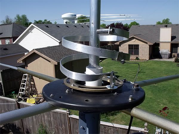
Close up shots of the current matching coil.
-
- Frequent Keyer
- Posts: 69
- Joined: Friday 8th Apr 2011, 1:45
- First Name: Charles
- Location: NW Arkansas
- Contact:
Re: .64 Homebrewed Antenna
Because someone asked for it:
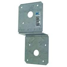
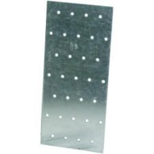
I used two of these: and one of these:
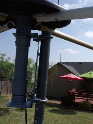
I straightened the Z plates into L's, and combined them with the mending plate to make a large C flange using two C clamps for attaching it all to a mast.
In the upper end of the C flange I enlarged
the hole to receive one of these:
on the bottom end I mounted one of these:
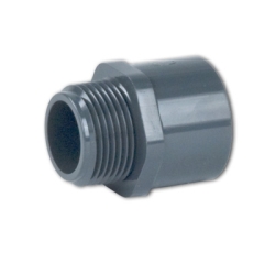
with one of these 1-1/2" close nipples screwed into a 1-1/2"PVC female adapter:
Of course, there is a 1-1/2" PVC tube between the top and bottom of the C flange and connectors.
Inside the bottom of the PVC tube is a smaller diameter PVC coupler sufficiently long enough to prevent the metal of the bracket from being in contact with the bottom of the vertical radiator.
The top spool end disc to which the radials are attached is fastened in this fashion:
A threaded female PVC coupler is screwed down onto the upward looking threads of the top 1-1/2" PVC male adapter at the top of the mounting flange and is used for a nut.
Another male PVC adapter is screwed downward into that coupler. At this point is where the spool end disc is placed.
Epoxy will prevent water from getting down into the mounting section when applied around the vertical radial, and if applied around the disc to adapter connection will secure the disc from rotating in a manner superior to my choice of silicone, however, I am subject to take the whole thing apart for a future project and reuse it all, so I used silicone because it isn't permanent.